Drawing Preparation
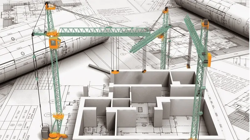
Drawing in civil engineering refers to the graphical representation of a structure, system, or project that is essential for planning, designing, and constructing buildings, roads, bridges, and other infrastructure. These drawings serve as a visual communication tool between engineers, architects, contractors, and clients, providing detailed and precise information for the construction process. Civil engineering drawings are typically created using computer-aided design (CAD) software, though hand-drawn sketches are still used in some cases.
Types of Civil Engineering Drawings
- Architectural Drawings:
- Purpose: These drawings represent the design of the building, focusing on the layout, dimensions, and aesthetic features of the project.
- Common Drawings:
- Floor Plans: Show the layout of rooms, spaces, and features on a particular floor.
- Elevations: Depict the exterior view of the building from different sides, showing windows, doors, rooflines, and materials.
- Sections: Vertical slices through the building, showing the internal structure, including heights, materials, and construction details.
- Detail Drawings: Focus on specific components of the building, such as doors, windows, staircases, and other elements.
- Structural Drawings:
- Purpose: Structural drawings represent the design and layout of structural elements, ensuring the safety, stability, and strength of a building or infrastructure.
- Common Drawings:
- Foundation Plans: Show the layout of the foundation, including footings, piles, and any other supporting elements.
- Beam and Column Plans: Display the placement and dimensions of beams and columns in the structure.
- Slab Plans: Show the layout of floor slabs, including thickness, material, and reinforcement details.
- Reinforcement Detailing: Provide the exact specifications for reinforcing steel, such as bar sizes, spacing, and bending schedules for beams, columns, and slabs.
- Structural Sections: Show cross-sectional views of the structure, detailing the dimensions, material properties, and reinforcement.
- Site Plans:
- Purpose: These drawings focus on the layout of the entire project site, including the position of buildings, roads, utilities, and landscaping.
- Common Drawings:
- Topographical Plans: Show the contour and elevation of the land, including any changes to be made during construction, such as grading and excavation.
- Drainage and Sewer Plans: Show the layout of stormwater drainage and sewage systems, including the locations of pipes, manholes, and catch basins.
- Utility Plans: Represent the location of utilities like water, electricity, gas, and communication lines within the site.
- Roads and Pavement Plans: Show the layout and dimensions of roads, paths, parking areas, and other paved surfaces.
- Masonry and Concrete Drawings:
- Purpose: These drawings provide detailed instructions on the design and construction of masonry and concrete elements, such as walls, foundations, and slabs.
- Common Drawings:
- Concrete Mix Designs: Specify the composition and proportions of concrete used for various components of the project.
- Masonry Details: Include drawings for brick, stone, or block walls, detailing sizes, mortar joints, and reinforcement.
- Slab Details: Show detailed information for cast-in-situ or precast concrete slabs, including reinforcement arrangements.
- Mechanical, Electrical, and Plumbing (MEP) Drawings:
- Purpose: MEP drawings represent the mechanical, electrical, and plumbing systems within a building or infrastructure.
- Common Drawings:
- HVAC Drawings: Show the heating, ventilation, and air conditioning systems, including duct layouts, air handling units, and piping.
- Electrical Drawings: Represent the electrical systems, including circuit layouts, panel boards, wiring diagrams, and lighting plans.
- Plumbing Drawings: Illustrate the water supply, drainage, and sewage systems, including pipe layouts, fixtures, and valves.
- Road and Highway Drawings:
- Purpose: These drawings are used in the design and construction of roads, highways, and other transportation infrastructure.
- Common Drawings:
- Road Alignment Plans: Show the horizontal and vertical alignment of the road, including curves, gradients, and intersections.
- Cross-Section Drawings: Represent the cross-sectional profile of the road, including layers of materials (subbase, base, and surface), drainage, and utilities.
- Pavement Details: Show the design of pavement layers and materials, including specifications for asphalt or concrete mixes.
- Traffic Control Plans: Illustrate traffic flow, signals, signage, and other elements related to road safety and regulation.
- Environmental and Landscaping Drawings:
- Purpose: These drawings are created for projects that involve landscape design, environmental protection, and green infrastructure.
- Common Drawings:
- Landscape Layouts: Show the placement of plants, trees, paths, and other landscaping elements around a building or infrastructure.
- Stormwater Management Plans: Illustrate how the site will manage rainwater, including retention basins, swales, and infiltration systems.
- Environmental Impact Drawings: Depict areas that will be affected by construction, highlighting measures for soil erosion control, habitat protection, and environmental restoration.